TOCForceMomentCoupleSystem of Forces Draft for Information Only
ContentEquilibrium of Rigid Body
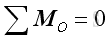
Equilibrium of Rigid BodyA rigid body is in static equilibrium state when the rigid body remains stationary and is not accelerating in any way. In other words, a rigid body is in equilibrium when both the resultant force and the resultant moment are zero for all the forces and couples acting on it. Through system of forces transformation, an equivalent system of forces can be reduced to a force vector and a couple vector. Therefore the resultant force and the resultant couple vectors acting on the rigid body are equal to zero. That is:
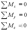
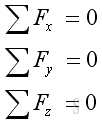
Or in terms of rectangular components:
In other words, there is no translational and rotational motion when an object is in static equilibrium state. 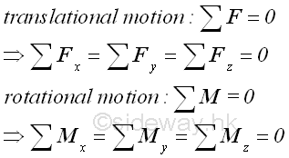
Free-BodyIn engineering static application, a rigid body is in equilibrium when the systems of external forces cause no translational and rotational motion to the rigid body since the resultant force and resultant memont on the rigid body are zero. For example, a hanging mass from the ceiling 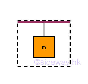
When solving the equilibrium problem of the considered body, in order to focus only on the interested body instead of the whole system, the interested body should be isolated from other bodies as a free body. According to Newton's third law, each applied force will have a reaction force of equal in magnitude and opposite in direction acting on the interacting bodies. Therefore, all the surrounding uninterested objects can be stripped away by replacing with the corresponding reaction force acting on the interesed body. For example, the interested objects are the mass and string. 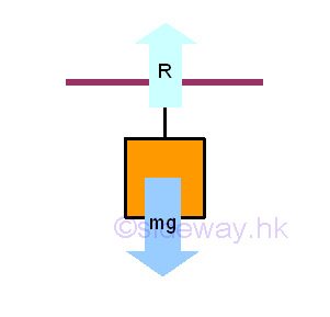
Therefore, a free body diagram can be drawn by adding a reaction force to replace the force due to the ceiling, while the body force due to the body mass remains unchange. 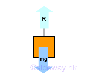
Since the hanging string is also not an interested body, Imply the free body diagram of the body mass is : 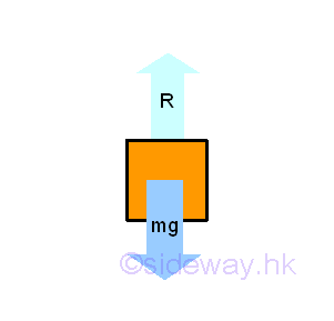
Free-Body DiagramImportant steps of constructing the free-body diagram are:
©sideway ID: 120200059 Last Updated: 2/15/2012 Revision: 0 Ref: References
Latest Updated Links
  Nu Html Checker Nu Html Checker  na na |
 Home 5 Business Management HBR 3 Information Recreation Hobbies 9 Culture Chinese 1097 English 339 Travel 45 Reference 79 Hardware 55 Computer Hardware 261 Software Application 213 Digitization 37 Latex 52 Manim 205 KB 1 Numeric 19 Programming Web 289 Unicode 504 HTML 66 CSS 65 SVG 46 ASP.NET 270 OS 431 DeskTop 7 Python 72 Knowledge Mathematics Formulas 8 Set 1 Logic 1 Algebra 84 Number Theory 206 Trigonometry 31 Geometry 34 Calculus 67 Engineering Tables 8 Mechanical Rigid Bodies Statics 92 Dynamics 37 Fluid 5 Control Acoustics 19 Natural Sciences Matter 1 Electric 27 Biology 1 |
Copyright © 2000-2026 Sideway . All rights reserved Disclaimers last modified on 06 September 2019
 and
and
 and
and