
TOCForceMomentCoupleSystem of ForcesStatic EquilibriumStructure AnalysisDistributed Force Draft for Information Only
Content
Applications of
Friction Forces
Applications of Friction ForcesFrictional forces are also found in many common practical tools and machines with rotating members. Thrust BearingsBesides the lateral supports, thrust bearings are also used for rotating members in tools and machines. Thrust bearings are usually used for providing axial support to rotating shafts and axles. If there is no lubrication between the rotating axle and the bearing, the disk friction is the dry friction between two contact surfaces only. In general, there are two types of thrust bearing i.e. the end bearing and collar bearing. An end bearing provides a full circular supporting area to the shaft, while the collar bearing provides a ring-shaped supporting area with an opening. For example, a wheel is rigidly mounted on an a hollow driving shaft which is supported by an end bearing on the closed end and a collar bearing on the open end. The axial loads acting on the end bearing and the collar bearing are equal to P. 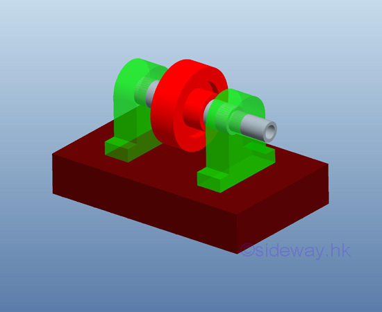
Because of the presence of friction forces between the planar contact surfaces of the shaft and the bearings, a couple of M is needed to maintain the wheel rotating at constant speed when an axial force P which forcing the shaft end to contact with the fixed bearing, is applied to shaft. For an uniform pressure distribution over the area of contact surfaces, an elemental normal force ΔN can be expressed in terms of the pressure due to the applied force P on an element area ΔA. And the corresponding elemental friction forces ΔF of each elemental area ΔA are reacted accordingly. Each reactive friction force ΔF generates reactive moment ΔM about the axis of the shaft. The summation of all elemental reactive friction moments ΔM due to the reactive friction forces over the contact surfaces is equal to the same magnitude of the applied couple M but opposite in sense. 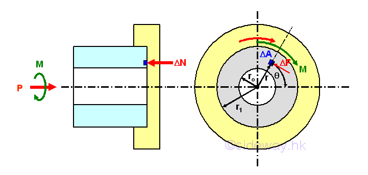
The magnitude of the elemental moment ΔM is. 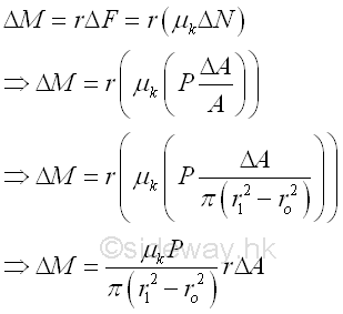
And the magnitude of the couple M about the axis can be determined by reducing the elemental area to infinitesimal element dA, imply. 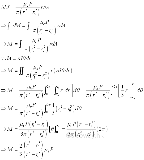
If the shaft is a solid shaft, and not a hollow shaft, the magnitude of the moment of the force of disk friction is 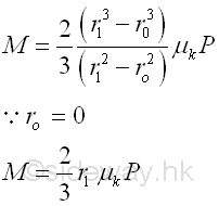
The couple M can be represented by a single force at a single point between the contact surfaces of the shaft and bearing. Imply. 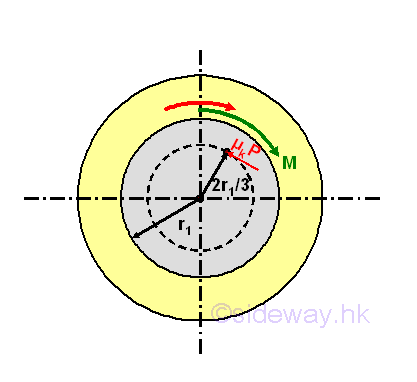
The disk friction is also used in other mechanical devices like disk clutches. In this case, the largest torque transmitted by the disk clutch before slippage can also be determined by replacing the coefficient of kinetic friction μk with the coefficient of static friction μs. WheelsWheel is a common rotating components used in tools and machines. A rolling wheel is a wheel rotating on an axle. A rolling wheel is usually used for supporting heavy loading during transporting. When a wheel is rotating, the contact point of the rolling wheel with the ground does not have relative motion with the ground. And therefore the applied force P need to overcome the large friction force due to the direct surface contact of the heavy load W on the ground. Considering a single wheel with loading W, 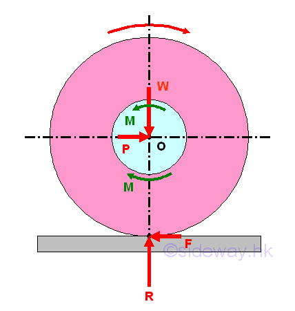
When the applied force P is applied to the left hand side of the wheel, the wheel is rotating clockwise on the stationary axle. The load W is moved by the applied force P when the applied force P can generate a clockwise couple of M to overcome the reactive counterclockwise couple due to the kinetic friction force between the contact surfaces of the axle and wheel and to maintain the wheel rolling at constant speed. The static friction force F between the contact surfaces of the wheel and ground will resist sliding and acts as the reactive friction force of the applied force to overcome the reactive counterclockwise couple due to the kinetic friction force between the contact surfaces of the axle and wheel. If there is no friction between the wheel and the ground, there is no external turning force acting on the wheel, the couple M due to the axle friction will be zero. The axle friction will hold the wheel in place, and thus, the wheel will slide on the ground without turning in its rotating and bearing assembly. Since a wheel hub usually has a small radius and equipped with a very smooth bearing, the applied force P needed to move the load W on wheel is therefore much less than the required force to move the heavy load W on the ground. If there is no axle friction between the axle and the wheel, the couple M becomes zero also. The forces P and F needed to overcome the couple M reduces to zero also. Since there is no relative motion at the point of contact between the wheel and the ground, the reactive static friction between the wheel and the ground will turn the wheel about its axis of rotation. A free rolling wheel can roll freely on a horizontal ground. The forces acting on the free body reduces to the load W and the reaction R only. 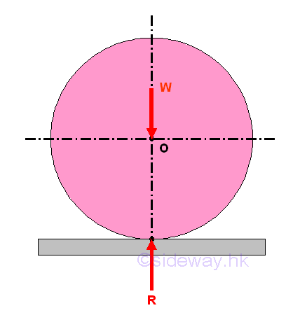
Besides the resistance of axle friction, there is another type of resistance to resist the motion of a rolling wheel. In practical applications, the contact surfaces between the wheel and the ground will be deformed slightly under the load W, thus the contact between the wheel and the ground does not take place at a point. For example, a rigid wheel will deform the soft ground surface. Since the reaction forces react over the area of contact, the point of application of the resultant reaction force R will shift slightly to the right at point B and is away from the vertical line of action which passing through the centre O. Similarly, the load W is moved by the applied force P when the applied force P can generate a clockwise couple to overcome the counterclockwise couple due to the moment of load W about B and to maintain the wheel rolling at constant speed. 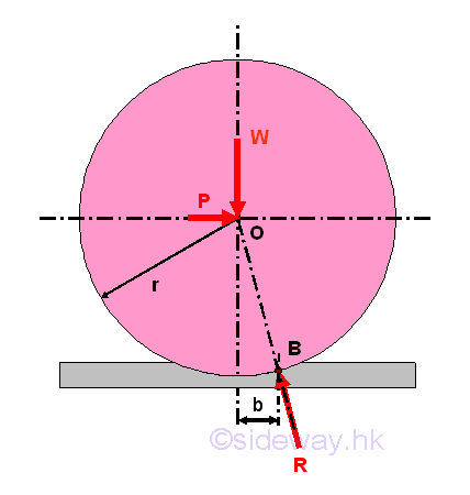
By taking moment about B, 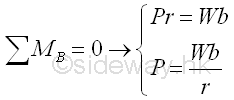
The distance b is called the coefficient of rolling resistance and is expressed in the unit of length, e.g. millimeter. ©sideway ID: 120800014 Last Updated: 8/17/2012 Revision: 0 Ref: References
Latest Updated Links
  Nu Html Checker Nu Html Checker  na na |
 Home 5 Business Management HBR 3 Information Recreation Hobbies 9 Culture Chinese 1097 English 339 Travel 45 Reference 79 Hardware 55 Computer Hardware 261 Software Application 213 Digitization 37 Latex 52 Manim 205 KB 1 Numeric 19 Programming Web 289 Unicode 504 HTML 66 CSS 65 SVG 46 ASP.NET 270 OS 431 DeskTop 7 Python 72 Knowledge Mathematics Formulas 8 Set 1 Logic 1 Algebra 84 Number Theory 206 Trigonometry 31 Geometry 34 Calculus 67 Engineering Tables 8 Mechanical Rigid Bodies Statics 92 Dynamics 37 Fluid 5 Control Acoustics 19 Natural Sciences Matter 1 Electric 27 Biology 1 |
Copyright © 2000-2026 Sideway . All rights reserved Disclaimers last modified on 06 September 2019