
TOCForceMomentCoupleSystem of ForcesStatic Equilibrium Draft for Information Only
Truss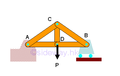
Truss is one of the most common type of engineering structure, e.g. bridges and building. A truss is only constructed with straight members connected at connecting joints by hinge pins located at the two ends of each member. A frictionless pin at the joint implys no rotational motion is transmitted through the joint. No member in the truss is continuous through a joint. Therefore, member in the truss behaves like a short link and only tensile and compressive force can be transmitted between the end joints in static equilibrium. 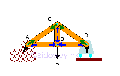
Since forces can only be applied at the joints of a member, a truss member is a two-force member. 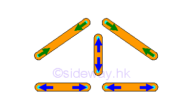
Usually, gusset plates are used for connecting the intersecting elements at the joint to eliminate the assembly sequence problem or may be in sometimes make the structure more stable. Although the original joint design of a truss is a fictionless hinge pin, truss member can also be rigidly connected because there is little impact of the force flow in a completely constrained and kinematically determinate structure. Since when designing a truss, the axial stiffness of the truss members is already sufficiently large enough to maintain the structure in the stable working condition and to ensure the bending restraint required at the connecting joint is negligible also. 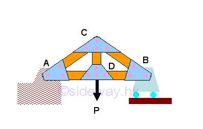
In truss structure design, the truss members are relatively slender for providing axial stiffness only. Since the truss members are not design for supporting lateral load, all loading can only be applied to the joint. Therefore, a system of stringers and cross beams are needed for any loading which cannot be applied onto the joints. For example, truss subject to a distributed load, or a concentrated load between two joints. In general, the weight of member is much smaller that the member axial force, the weight of member can often be neglected. However, when the member weight should be considered, the member weight can be assumed to be shared as loadings that being applied to the joints at two ends of the member. ©sideway ID: 120200069 Last Updated: 3/12/2012 Revision: 1 Ref: References
Latest Updated Links
  Nu Html Checker Nu Html Checker  na na |
 Home 5 Business Management HBR 3 Information Recreation Hobbies 9 Culture Chinese 1097 English 339 Travel 45 Reference 79 Hardware 55 Computer Hardware 261 Software Application 213 Digitization 37 Latex 52 Manim 205 KB 1 Numeric 19 Programming Web 289 Unicode 504 HTML 66 CSS 65 SVG 46 ASP.NET 270 OS 431 DeskTop 7 Python 72 Knowledge Mathematics Formulas 8 Set 1 Logic 1 Algebra 84 Number Theory 206 Trigonometry 31 Geometry 34 Calculus 67 Engineering Tables 8 Mechanical Rigid Bodies Statics 92 Dynamics 37 Fluid 5 Control Acoustics 19 Natural Sciences Matter 1 Electric 27 Biology 1 |
Copyright © 2000-2026 Sideway . All rights reserved Disclaimers last modified on 06 September 2019