
TOCForceMomentCoupleSystem of ForcesStatic Equilibrium Draft for Information Only
Content
Frame
Frame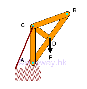
Frame is another common type of structure to support load. Frame is also usually a fully constrained stationary structure like the truss. The main difference be frame and truss is the constructing member. In general, a frame should contain at least one multiple force member with forces, which are not all along the direction of member axis, acts on three or more positions the frame member. The forces acting upon the frame member can also be determined similar to the forces analysis in truss. The frame is in equilibrium, both the connecting joints and the frame members on the frame are in equilibrium also. For a two-force member in static equilibrium, only tensile and compressive force along the axis of frame members can be transmitted between the applied forces. But for a multi-forces member, forces acting upon the frame member are in equilibrium, but the directions of resultant forces acting upon the frame member are to be determined. 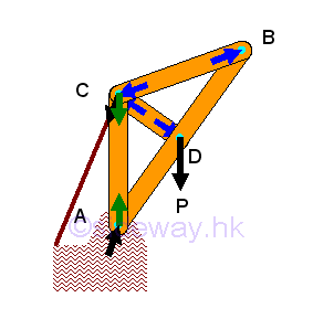
The force in the two-force frame member can be assumed either tensile or compressive, the sense of the direction will confirm whether the assumption is correct or not. And by Newton's third law, the action and reaction forces between a joint pin and a frame member are always equal and opposite. Therefore at each joint, every connected frame member will exert an force of equal in magnitude and line of action, and opposite in sense on the joint pin. Since the frame is in equilibrium, the resultant force of all forces including frame reactions, applying loads and reactions acting on the joint pin is equal to zero. Besides the reaction force of a two-force frame member will also transmitted to the multi-force frame member through the joint pin also. Since the directions of both the two-force member and the reaction forces are known, the forces act upon the mult-force frame member can also be marked on the free body diagram of the multi-force frame member. In general, forces in a multi-force frame member can usually be expressed in two rectangular forces. 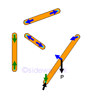
Stability:In frame design, sometimes the supports and connections of the frame provides additional constraints to stabilize the shape of the frame. And therefore the frame will collapse if the frame is detached from the supports and connections. For example, if the string for retaining the frame support is replaced by a frame member, the frame structure becomes unstable and collapsible after detached from the supports. 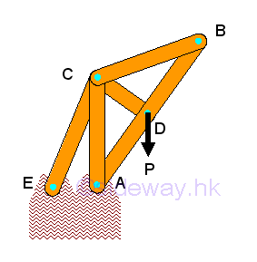
Since the frame is collapsible after detached from the supports, the frame cannot be considered as a rigid body. And in general, the three equilibrium equations of a rigid body also cannot determined the four unknown reactions of the collapsible frame. Since the three equilibrium equations obtained from a collapsible, non-rigid structure is only the necessary conditions for the collapsible structure in equilibrium, but these conditions are not sufficient conditions for the sturcture to be stable as a rigid body. By considering the frame as two distinct rigid component parts of the frame, two individual free body diagrams for the frame can be drawn. 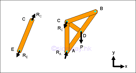 For each componenet part, there are four unknown forces. And for each distinct
rigid component part, three independent equilibrium equations can be written.
There are totally eight unknown forces and six equilibrium equations. By
Newton's third law, two forces at the connecting joint in the two rigid
component parts are equal and opposite. Thereforce the eight unknown forces can
be reduced to six unknown forces and all unknown force can then be determined by
the six independent equilibrium equations.
For each componenet part, there are four unknown forces. And for each distinct
rigid component part, three independent equilibrium equations can be written.
There are totally eight unknown forces and six equilibrium equations. By
Newton's third law, two forces at the connecting joint in the two rigid
component parts are equal and opposite. Thereforce the eight unknown forces can
be reduced to six unknown forces and all unknown force can then be determined by
the six independent equilibrium equations.
Determinacy:From the above example, a non-rigid, collapsible structure with suitable constraints is rigid and statically determinate. In general, the necessary condition for a structure to be rigid and statically determinate is the number of unknown forces equal to the number of the independent equations. And the structure should also be properly constrained. The equilibrium equations and unknowns of the frame can be obtained from drawing free-body diagram for each rigid component parts or for each frame member. If there are more unknown forces than the independent equilibrium equations, the structure is statically indeterminate. If there are more independent equilibrium equations than unknown forces, the structure is unstable, or non-rigid. Only if the number of unknown forces is equal to the number of independent equilibrium equations, the unknown forces can be determined. If all unknowns can be determined and all independent equilibrium equations can be satisfied under general loading conditions, the structure is said to be statically determinate and rigid. However, if there is improper arrangement of frame members and supports, all unknowns cannot be determined and all equilibrium equations cannot be satisfied, and the structure is said to be statically indeterminate and non-rigid. Forces Analysis: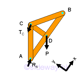
For a completely constrained rigid frame, the number of unknown reactions provided by the supports and connections is equal to three and all the unknown reactions of the frame is statically determinate and can be determined by the three independent equilibrium equations. 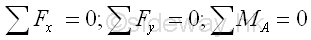
Therefore 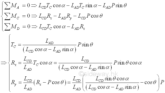
Forces in a two-force member can only be either tensile or compressive forces. Forces acting upon the multi-force member are to be determined. Forces acting on a connecting joint should be in equilibrium. In this example, however, forces in the multi-force member are forces with two rectangular components, there are three unknown forces at all connecting joints. Therefore the three unknown forces in frame members AC, CD, and CB should be determined using the method of sections by selecting the sectional component part with the frame member AB. 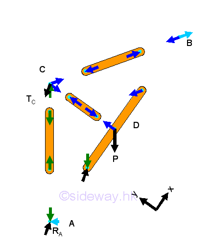
Since there is only one frame member in the sectional component part, the force analysis of the sectional component part is same as the force analysis of the frame member. Imply
Therefore: 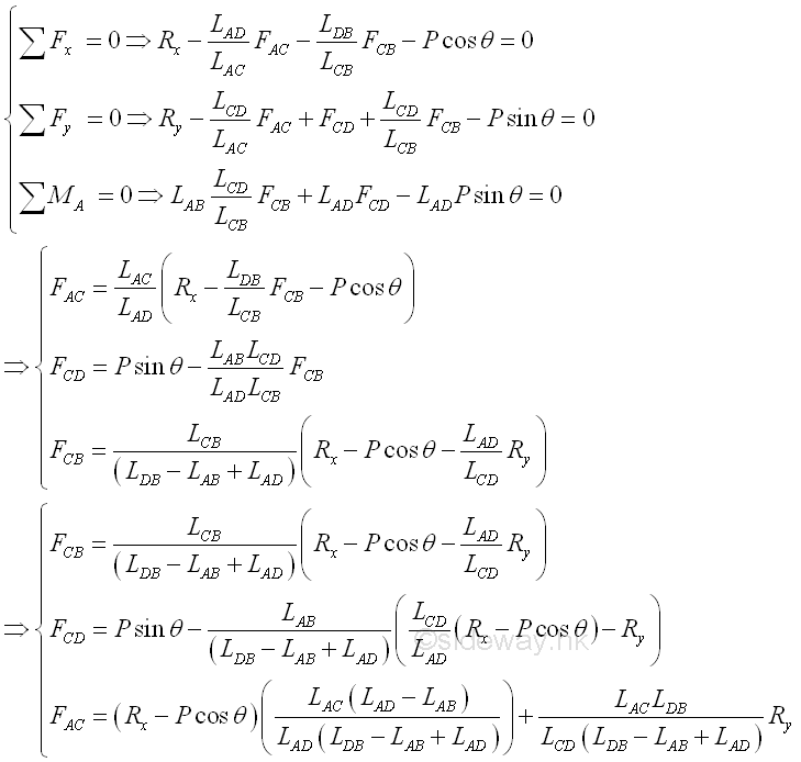
©sideway ID: 120300010 Last Updated: 3/20/2012 Revision: 0 Ref: References
Latest Updated Links
  Nu Html Checker Nu Html Checker  na na |
 Home 5 Business Management HBR 3 Information Recreation Hobbies 9 Culture Chinese 1097 English 339 Travel 45 Reference 79 Hardware 55 Computer Hardware 261 Software Application 213 Digitization 37 Latex 52 Manim 205 KB 1 Numeric 19 Programming Web 289 Unicode 504 HTML 66 CSS 65 SVG 46 ASP.NET 270 OS 431 DeskTop 7 Python 72 Knowledge Mathematics Formulas 8 Set 1 Logic 1 Algebra 84 Number Theory 206 Trigonometry 31 Geometry 34 Calculus 67 Engineering Tables 8 Mechanical Rigid Bodies Statics 92 Dynamics 37 Fluid 5 Control Acoustics 19 Natural Sciences Matter 1 Electric 27 Biology 1 |
Copyright © 2000-2026 Sideway . All rights reserved Disclaimers last modified on 06 September 2019