
TOCForceMomentCoupleSystem of ForcesStatic EquilibriumStructure AnalysisDistributed ForceFriction ForceInternal Force Second Moment of an AreaMoment of Inertia of Plane AreaMoment of Inertia of Composite AreaPrincipal Moments & Product of inertia Draft for Information Only
ContentGraphical Method of Second Moment of Area
Graphical Method of Second Moment of AreaGraphical method for performing coordinate transformations is useful for visualizing the relationship between the second moment of area and the orientation coordinate system considered at a fixed point. Mohr's CircleMohr's Circle, named after Otto Mohr, is a graphical representation of the relation between the rectangular moments and products of inertia of area about a rectangular coordinate system through a fixed point. Since the coordinate transformation is a fuction of rotating angle, the transformation equations of second moment of an area can be considered as parametric equations of a circle. Imply 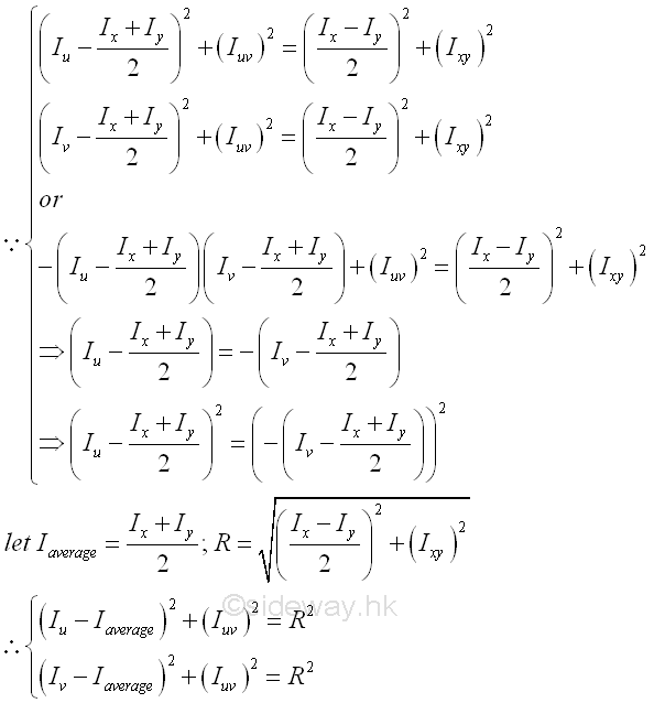
That is parametric equations of a circle with centre (Iaverage,0) and radius R. The coordinates of points lying on the circle are (rectangular moment of inertia Iu or Iv , the product of inertia Iuv ) which are function of the rotating angle θ about the origin of the reference coordinate axes xy. Construction of Mohr's CircleConsider an area A with known rectangular moments, Ix and Iy, where the value of Ix is greater than Iy and product of inertia Ixy about rectangular coordinate axes xy passing through point O, which can be located inside or outside the area A. Assume the product of inertia Ixy with positive sign, Let Ip and Iq be the principle moments of inertia with respective to rectangular coordinate axes pq assing through point O. let Iu and Iv, be the unknown rectangular moments and Iuv be the unknown product of inertia about rectangular coordinate axes uv passing through point O, Imply 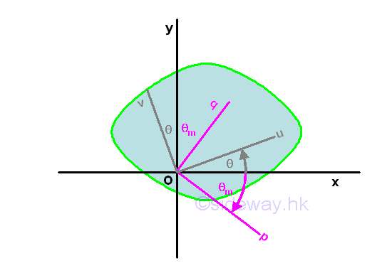
The Mohr's circle is drawn on a rectangular coordinate system with horizontal axis, the rectangular moments of inertia Ix and Iy, and vertical axis, the product of inertia Ixy. The Mohr's circle is located by the known rectangular moments of inertia Ix and Iy and the product of inertia Ixy. Since the sum of rectangular moments Ix+Iy, about a fixed point is a constant regardless of the orientation of the coordinate axes, the horizonal coordinate of the centre M of the circle is equal to the average of the sum of rectangula moments (Ix+Iy)/2. Since the square of R is also an invarient under the rotation of the rectangular coordinate axes, the vertical coordinate of the centre M of the circle is equal to zero. After defining the coordinate axes and centre of the Mohr's circle, the two points for the known moments of inertia can be plotted on the Mohr's circle. Because the rectangular moments is always positive and Ix is assumed to be greater than Iy , the location of Ix is on the right hand side of Iy along the horizontal axis. As the product of inertia, Ixy is positive assumed in the area A, in order to have the same sign convention as used in the area diagram, .a point X of coordinate (Ix,Ixy) is marked above the horonzeontal axis. Then a point Y of coordinate (Iy,-Ixy) are marked on the circle. However, the value of the product of inertia Ixy can be positive, negative and zero, so the location of points X and Y should be marked on the circle accordingly. The orientation of line segment XY represents the orientation of the coordinate axes xy. Therefore, line segment XY is related to the rectangular moments of inertia Ix and Iy and the product of inertia Ixy about coordinate axes xy through the fixed point O. 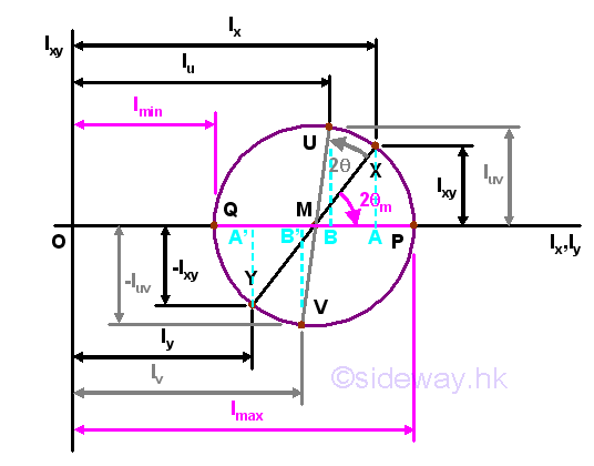
Mathematically, principal axes and principal moments of inertia about the fixed point O can be determined by differentiation. But principal axes and principal moments of inertia about the fixed point O can also be determined by the Mohr's circle graphically. Since the product of inertia of area about the principal axes is equal to zero, the points of principal moments lying on the Mohr's circle should also lie on the horizontal axis at which Ipq is equal to zero. Therefore a point P of coordinate (Imax,0) and a point Q of coordinate (Imin,0) can be marked on the circle. According to the method of constructing the Mohr's circle, the principal moment of inertia about the axis p is equal to Imax and the principal moment of inertia about the axis q is equal to Imin. The orientation of line segment PQ represents the orientation of the coordinate axes pq. Therefore, line segment PQ is related to the rectangular moments of inertia Ip and Iq and the product of inertia Ipq about coordinate axes xy through the fixed point O. The value of principal moments of inertia about the fixed point O from Mohr's circle is same as the mathematical calculation. Imply 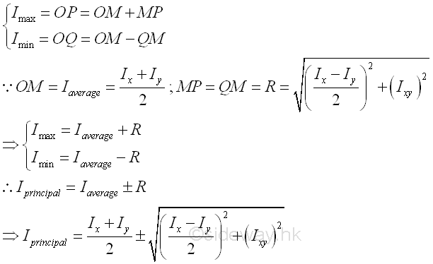
Usually, the values of moments of inertia and the direction of rotating angle are the same in both the area diagram and the mohr's circle, but the magnitude of the rotating angle in the mohr's circle is twice the rotating angle in the area diagram. Therefore the angle between line segments XY and PQ are twice the rotating angle θm, i.e. 2cm. The relation of rotating angle in area diagram and Mohr's circle can be proved as following. 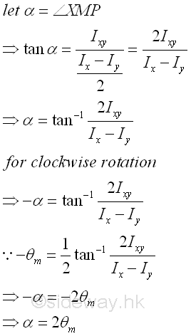
Since the angle between the line segment XY and the horizontal axis is determined, the known rectangular moments of inertia Ix and Iy and the product of inertia Ixy about coordinate axes xy through the fixed point O can then be expressed in terms of the angle of the orientation of the line segment XY in the Mohr's circle. Imply 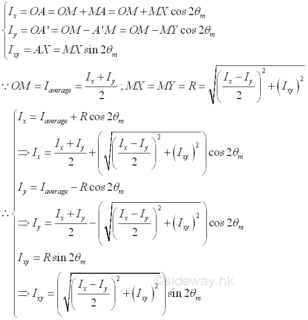
Similarly, the unknown rectangular moments of inertia Iu and Iv and the product of inertia Iuv about coordinate axes uv through the fixed point O can be obtained by Mohr's circle if the rotating angle of the coordinate axes uv is known. Mathematically, the unknown moments of inertia are. 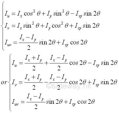
Since the line segment use to represent the coordinate axes in the Mohr's circle is of the same direction of rotation but twice the magnitude of the angle of rotation relative to the known line segment, the magnitude of the unknown rectangular moments of inertia Iu and Iv and the product of inertia Iuv about coordinate axes uv through the fixed point O can be expressed in terms of the the angle of the orientation of the line segment UV in the Mohr's circle. Imply 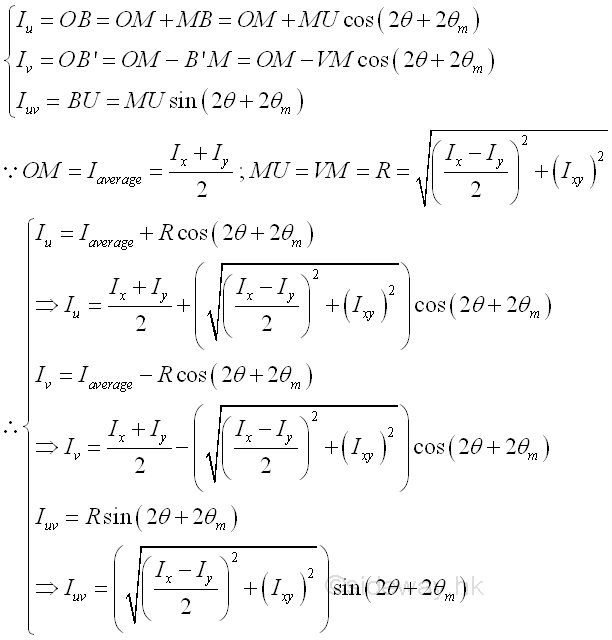
And the value is same as the results obtained by mathematical calculation. Imply 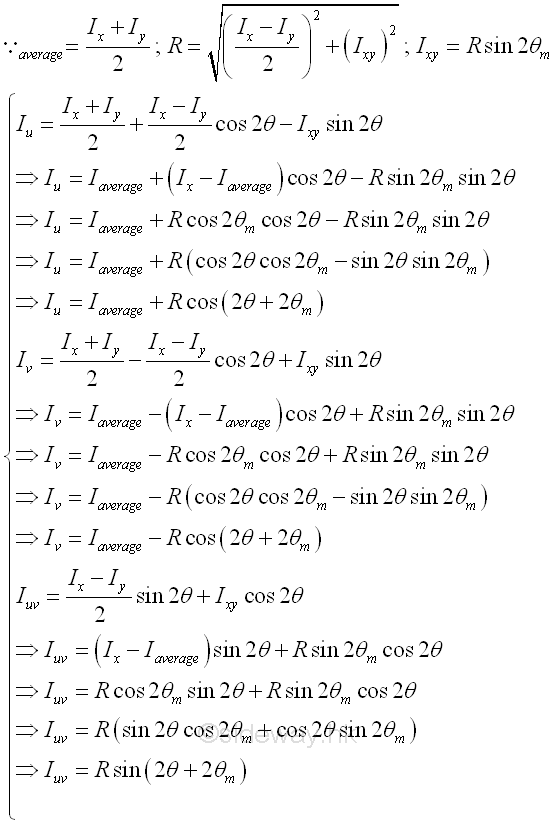
Land's CircleSimilar to the construction of a Mohr's circle, a Land's circle can be used to visualize the unknown rectangular moments of inertia Iu and Iv and the product of inertia Iuv about coordinate axes uv through the fixed point O, if the rectangular moments of inertia Ix and Iy, and the product of inertia Ixy about coordinate axes xy through the fixed point O is known. The main difference of the Land's circle method is both the magnitude and the direction of rotating angle of the coordinate system are the same in the area diagram and the Land's circle, which constructed by shifting the origin of rotation from the centre of the circle to the circumference of the circle and changing the diameter of the circle from the different of the known rectangular moments of inertia to the sum of the known rectangular moments of inertia on a rectnagular coordinate system aligned with the rectangular coordinate axes only. Construction of Land's CircleConsider the same area A, the Land's circle is drawn on a rectangular coordinate system with horizontal axis, the rectangular coordinate axis x, and vertical axis, the rectangular coordinate axis y. The Land's circle is located by the known rectangular moments of inertia Ix and Iy only. Since the sum of rectangular moments Ix+Iy, about a fixed point is a constant regardless of the orientation of the coordinate axes, the diameter of the Land's circle is equal to the sum of rectangular moments Ix+Iy. Since the rectangular moments of inertia is alwary positive, the Land's circle is drawn with centre M of the circle located on the vertical axis above the horizontal axis and the circle tangent to the horizontal axis. 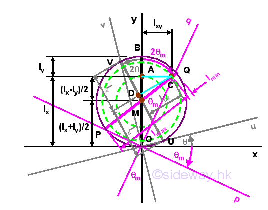
The known rectangular moments of inertia Ix and Iy are plotted on the vertical axis y. First, mark the line segment OA of length Ix, then mark the line segment AB of length Iy. The length of line segment OB is equal to the sum of the knwon rectangular moments of inertia Ix+Iy and is equal to the diameter of the Land's circle. And therefore the centre M of the Land's circle is eqaul to (Ix+Iy)/2 on the y axis. A concentric circle center M of radius (Ix-Iy)/2 can be constructed through point A. Therefore the mathematical solution of the principal moments of inertia about pq can be located on the Land's circle directly by constructing a line parallel to the coordinate axis x of length equal to the product of inertia Ixy throught point A. Since the product of inertia is assumed to be positive, the line is plotted from A rightward to C. The coordinate of point A is A(Ix,0). The coordinate of point C is C(Ix+Iy,0). The coordinate of point C is C(Ix,Ixy). A line can be drawn from from point C through the centre M to the other side of the circle cuting at point P. The length of line segment PC is equal to the maximum principal moment of inertia Ip. And another line can be drawn by extending the line segment PC from point C to cut the circle at point Q. The length of line segment CQ is equal to the minimum principal moment of inertia Iq. A coordinate axes pq related to the principal moments of inertia can also be constructed by connecting points Oand Q as the vertical axis q. Since angle CMA is equat to 2θm, angle QOB is equal to θm and is equal to the angle of rotation of the coordinate axes pq relative to the coordinate axes xy in same direction. Similarly a concentric circle center M of radius √(((Ix-Iy)/2)2+(Ixy)2) can be constructed through point C. Both values can be proved geometrically. Imply 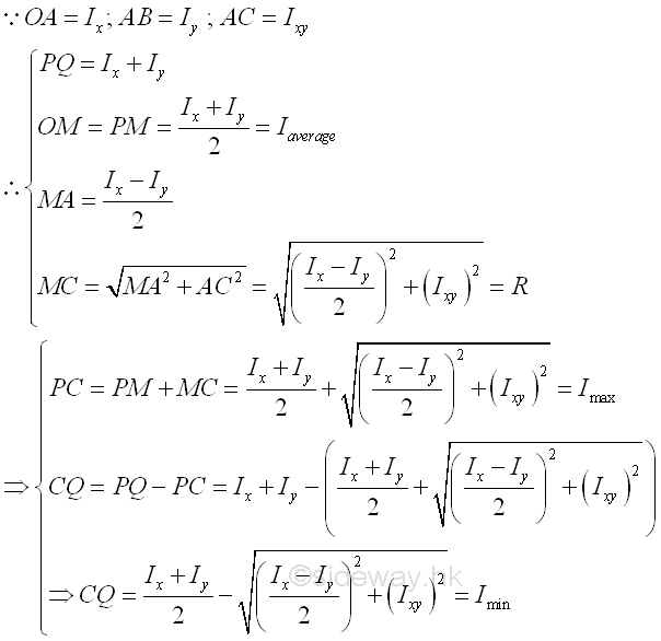
Similarly, the unknown rectangular moments of inertia Iu and Iv and the product of inertia Iuv about coordinate axes uv through the fixed point O can be obtained by Land's circle if the rotating angle of the coordinate axes uv is known. Since the coordinate axes in the Land's circle is of the same direction of rotation and same magnitude of the angle of rotation relative to the known line segment, the magnitude of the unknown rectangular moments of inertia Iu and Iv and the product of inertia Iuv about coordinate axes uv through the fixed point O can be determined by constructing a coordinate axes uv on the Land's circle with the same origin O. The vertical axis v of cooridnate axes uv will cut the Land's circle at point V. A line can be constructed by joining point V and M. The reference line segment UV can be drawn by extending the line segment VM from point M to cut the circle at point U. A perpendicular line can then be drawn from point C to cut the line segment UV at D. The length of line segment DC is equal to the product moment of inertia Iuv. The length of line segment UD is equal to the rectangular moment of inertia Iu. The length of line segment DV is equal to the minimum principal moment of inertia Iv. Values can be proved geometrically. Imply 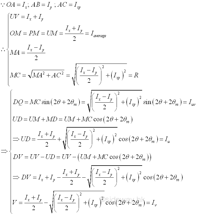
Momental EllipseThe ellipse of second moment of area or momental ellispse is another graphical method to find the unknown moments of inertia about coordinate axes uv with known princaipal moments of inertia about principal coordinate axes pq. Since the product of inertia about the rectangular principal axes is equal to zero. Imply 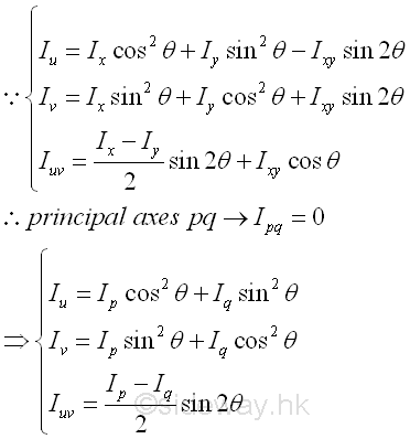
The ellipse of second moment of area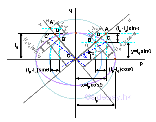
Consider the same area A with two known principal moments of inertia Ip, and Iq, an ellipse of second moment of area can be constructed on a rectangular cooridnate axes pq with axis p the horizontal axis and axis q the vertical axis through the fixed point O. The two values of principal moments of inertia are plotted on the rectangular coordinate accordingly and two concentric circles with centres at origin O of radii equal to Ip, and Iq are drawn respectively. The coordinate axes uv related to the unknown moments of inertia can be plotted by rotating the coordinated axes pq by an rotating angle of same magnitude and same direction as in area diagram. The coordinate axes uv cut the concentric circle at A, B, A, and B'. Construct a vertical line through A and a horizontal line through B. The two construction lines are cut at C. Similarly, construct a vertical line through A' and a horizontal line through B'. The two construction lines are cut at C'. A perpendicular line can then be drawn from point C to cut the line segment OA at D. Similarly, a perpendicular line can then be drawn from point C' to cut the line segment OA' at D'. The length of line segment OD is equal to the rectangular moment of inertia Iu, and the length of line segment OD' is equal to the rectangular moment of inertia Iv. While both the length of line segments CD or C'D' are equal to the product moment of inertia Iuv, Values can be proved geometrically. Imply 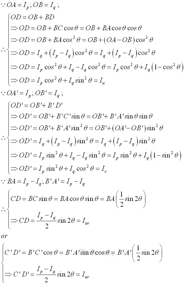
Since the sum of the rectangular moments of inertia is a constant. Imply 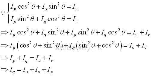
Consider the locus of C due to the rotating of the coordinate axis u, the coordinate of point C can be expressed in terms of the principal moments of inertia Ip and Iq, and the rotating angle θ. Imply 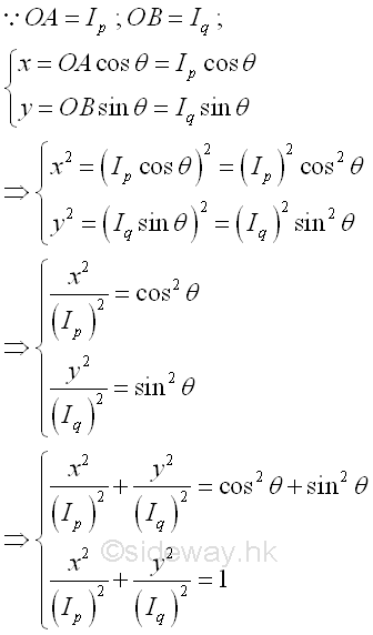
The equation of locus of point C represents an equation of an ellipse, i.e the ellipse of second moments of an area. The length of line segment OC is equal to 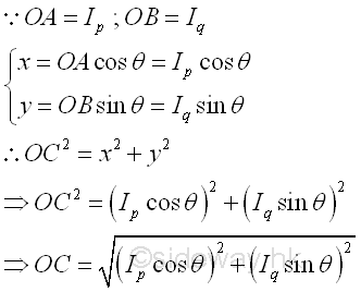
The angle between the line segment OC and the horizontal axis is equal to 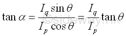
Momental Ellipse of Radii of Gyration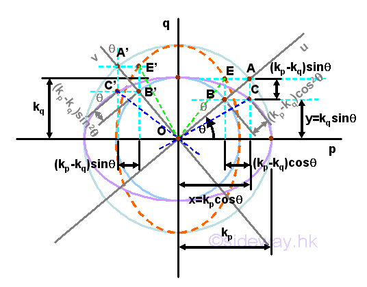
Consider the same area A with two known principal moments of inertia Ip, and Iq, an momental ellipse of area can be constructed on a rectangular cooridnate axes pq with axis p the horizontal axis and axis q the vertical axis through the fixed point O using the radii of gyration again. Imply 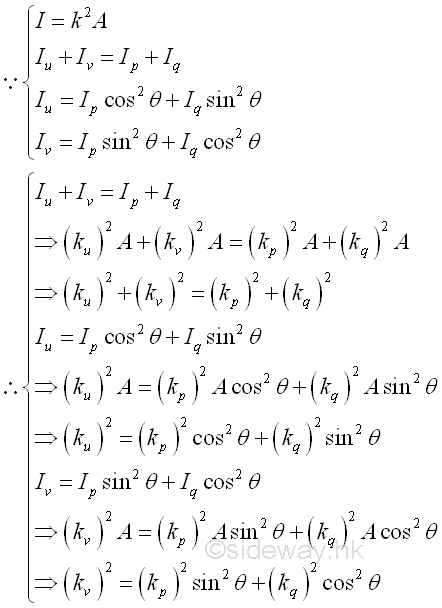
The two values of radii of gyration are plotted on the rectangular coordinate accordingly and two concentric circles with centres at origin O of radii equal to kp, and kq are drawn respectively. In order words, the scales of the two rectangular coordinate axes are changed respectively. The coordinate axes uv related to the unknown moments of inertia can be plotted by rotating the coordinated axes pq by an rotating angle of same magnitude and same direction as in area diagram. The coordinate axes uv cut the concentric circle at A, B, A, and B'. Construct a horizontal line through A and a vertical line through B. The two construction lines are cut at C. Similarly, construct a horizontal line through A' and a vertical horizontal line through B'. The two construction lines are cut at C'. A perpendicular line can then be drawn from point C to cut the line segment OA at D. Similarly, a perpendicular line can then be drawn from point C' to cut the line segment OA' at D'. Consider only the locus of C due to the rotating of the coordinate axis u, the coordinate of point C can be expressed in terms of the radii of gyration kp and kq, and the rotating angle θ. Imply 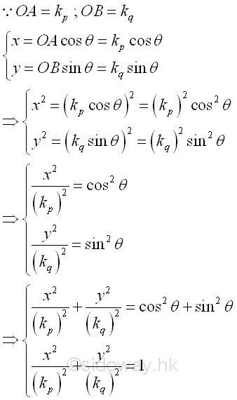
The equation of locus of point C represents an equation of an ellipse, i.e the momental ellipse of an area. Because of the change of scales of coordinate axes, the length of line segment OC is equal to the radius of gyration about the axis u after rotation. Imply 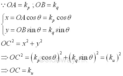
Similarly, a vertically ellipse can also be constructed with the major axis along the vertical axis by constructing another locus point E on the other side of the coordinate axes us. The equation of locus of point E represents an equation of an ellipse, i.e the vertical momental ellipse of an area. Imply 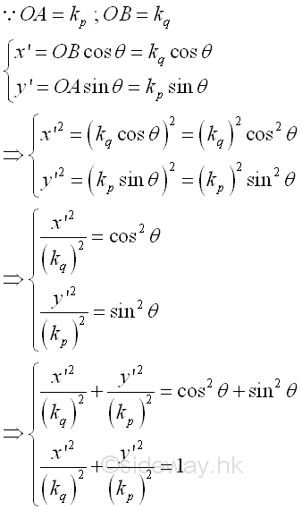
Because of the interchange of major axis and minor axis of the momental ellipse, the length of line segment OE is equal to the radius of gyration about the axis v after rotation. Imply 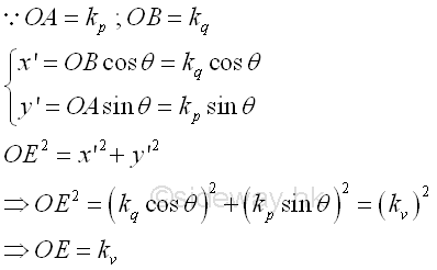
Or the radius of gyration can be obtained from the momental ellipse graphically by constructing a tangent line of the momental ellipse parallel to the coordinate axis. Imply 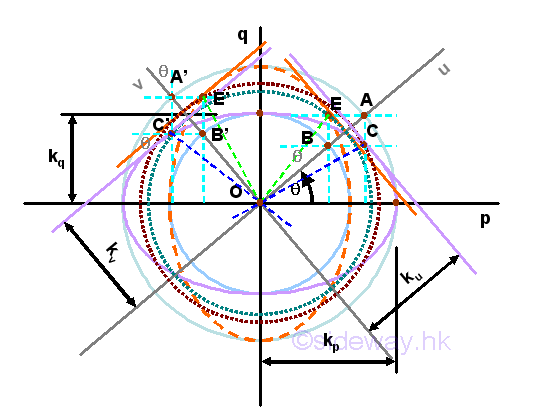
Values can be proved geometrically. For the horizontal momental ellipse. Imply 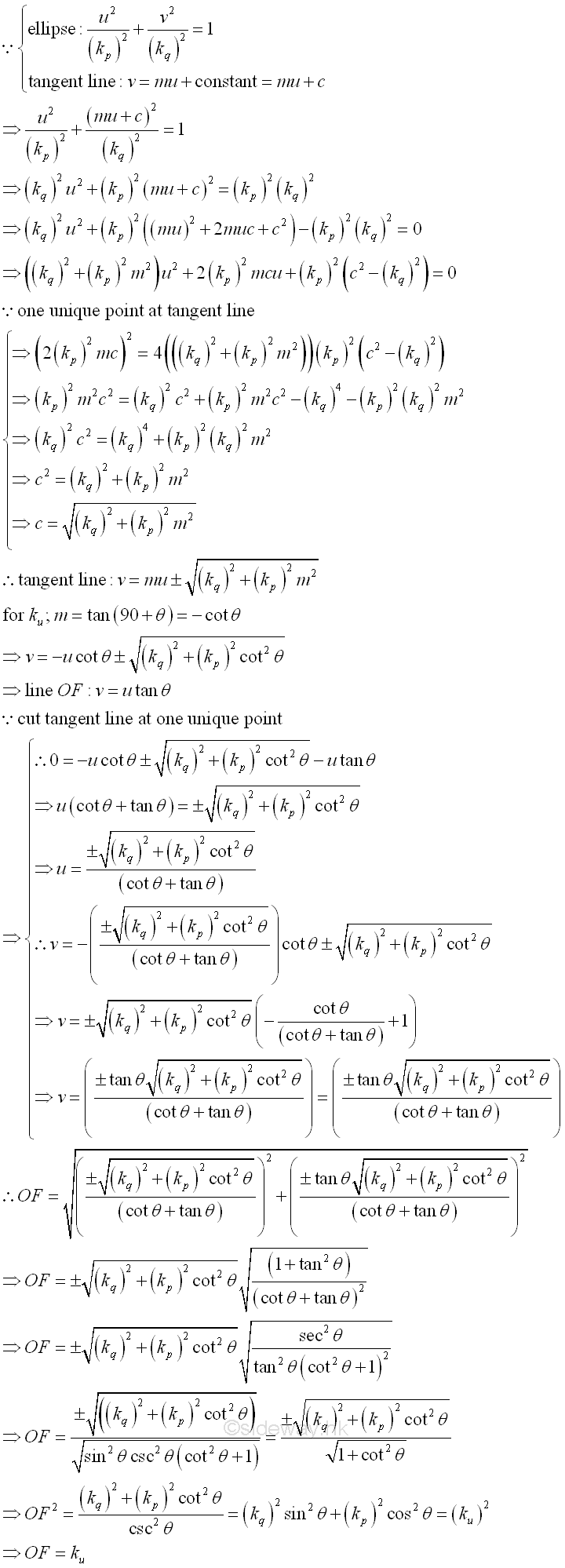
Momental Ellipse of Reciprocal of Radii of GyrationAnother way to plot the momental ellipse is the making use of the reciprocal of the radii of gyration. Imply 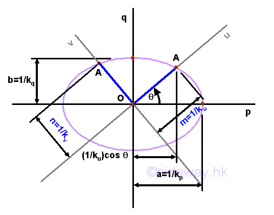
Consider the same area A with two known principal moments of inertia Ip, and Iq, an momental ellipse of area can be constructed on a rectangular cooridnate axes pq with axis p the horizontal axis and axis q the vertical axis through the fixed point O using the radii of gyration again. Imply 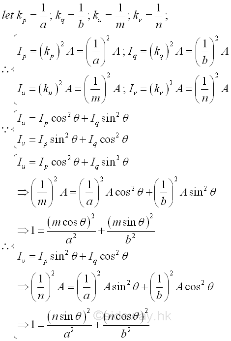
And the unknown moments of inertia about coordinate axes uv with known princaipal moments of inertia about principal coordinate axes pq is. 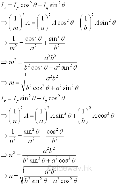
©sideway ID: 121000011 Last Updated: 11/1/2012 Revision: 0 Ref: References
Latest Updated Links
  Nu Html Checker Nu Html Checker  na na |
 Home 5 Business Management HBR 3 Information Recreation Hobbies 9 Culture Chinese 1097 English 339 Travel 45 Reference 79 Hardware 55 Computer Hardware 261 Software Application 213 Digitization 37 Latex 52 Manim 205 KB 1 Numeric 19 Programming Web 289 Unicode 504 HTML 66 CSS 65 SVG 46 ASP.NET 270 OS 431 DeskTop 7 Python 72 Knowledge Mathematics Formulas 8 Set 1 Logic 1 Algebra 84 Number Theory 206 Trigonometry 31 Geometry 34 Calculus 67 Engineering Tables 8 Mechanical Rigid Bodies Statics 92 Dynamics 37 Fluid 5 Control Acoustics 19 Natural Sciences Matter 1 Electric 27 Biology 1 |
Copyright © 2000-2026 Sideway . All rights reserved Disclaimers last modified on 06 September 2019